200-micron Fiber Enables New Cable Designs

A new generation of single-mode fibers with a smaller 200 micron coating dimension are now on the market. This paper, brought to you by OFS, shows how they enable novel compact cable designs that give telecom providers new options for their optical network.
Since single-mode fiber was first introduced in the early 1980s, little has changed in its basic geometric parameters. The core size has remained between 8-10 microns, the cladding of the glass has remained at 125 microns, and the coating is still 250 microns. Standardizing these dimensions has greatly improved interoperability and consistency across the optical network. Recently a new generation of single-mode fibers with a smaller 200 micron coating dimension has become available. This new dimension has enabled novel compact cable designs that give telecom providers new options for their optical network.
The case for crowded ducts
There are two trends that have become apparent in the deployment of modern high-performance networks. One is the need for low-count optical cables to connect single subscribers or buildings; the second is the need for very high-count optical cables to distribute large volumes of information. The average count in the second group continues to rise; today, some optical cables have well over 500 optical fibers in a single optical cable. In most cases, scaling up the optical cable design using current practices is the preferred approach, but sometimes this option is not available due to limited duct space. Most often, ducts are deployed in advance of the optical cable and the dimensions are fixed. In these situations an operator has two choices: limit the number of fibers deployed for the given link or deploy a new cable design with smaller dimensions than what is used traditionally. Further, microcables can have an economic advantage when existing ducts are subdivided with smaller microducts, which can be used to help avoid the costs of civil works and approval processes with local authorities.
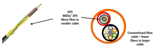
The figure above illustrates how microcables have evolved to twice the density that they were a few years ago. The conventional cable is 14 mm in diameter, while the newer design is 9.6 mm. Both cables have 288 fibers. The new design takes advantage of the new 200 micron coated fiber and is 36 per cent smaller.
The evolution of microcables has been enabled by both new design approaches and new materials. Key design modifications include:
- Placing fibers in smaller tubes
- Designing cables to be blown into the duct rather than pulled
New ITU-T G.657 fibers and new optical fiber coatings have allowed for tighter packing densities. Even with the space minimised between the fibers in these compact designs, the optical cables can meet industry-recommended crush requirements as well as low temperature performance requirements. Because blown cables are now the preferred deployment technology in Europe, fewer strength members need to be incorporated into the cable design. Together these new constraints have enabled the latest generation of smaller microcables.
The net result is a significant improvement in the density of fibers in optical cables. A few years ago, a cable diameter of over 10 mm was required for a 48-fiber cable design. Today, we can place 288 fibers in a cable that is smaller than 10 mm, clearly illustrating the great progress that has been made in this area. Achieving these targets are possible using 200 micron coated fibers as seen in the figure above.
Simply stated, as we reduce the size of the cable elements, a larger percentage of what remains in the cable is optical fiber. The 200 micron coated fiber cross sectional area is 46 per cent smaller than that of the 250 micron coated fiber. Thus, with no other changes to the cable design, we can expect that the cable dimensions can be reduced simply by reducing the coating thickness. That said, the new product must be both useable and reliable for the product to have any value.
Using 200 micron fiber
In the current issue of the ISO/IEC 60793-2-50 single-mode fiber specification, 200 microncoated fiber was included as an alternate coating dimension. The IEC optical fiber and cable working groups reviewed practical data as well as reliability data from several industry experts. Their conclusion was that 200 microns is a reasonable dimension for coated singlemode transmission fiber and should be included in the new standard. Further, reference is also made to this alternate coating dimension in Telcordia GR 20, due to be published soon. With the fiber now standardised, more service providers are seeing value in this product and are considering it for their networks.
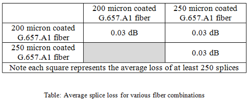
The 200 micron coated fiber works well in the field with current tools and practices. Conventional stripping tools effectively remove the acrylate coating. Once the coating is removed, the bare fiber has the same 125 micron dimension (diameter) as 250 micron coated fiber; therefore, cleaving and fusion splicing can be accomplished with the same tools as conventional fiber. Our internal splice studies show no difference between splicing like and dissimilar fibers. Average splice losses for various combinations of OFS’ AllWave® FLEX fiber using a Fitel S177 or S178 fusion splicer are shown in the table below:
With single fiber connectors, the fibers are up-jacketed before the connector is attached; again, the alternate coating dimension has little or no impact on single fiber connectors.
One key difference with 200 micron coated fibers is how they perform in ribbon structures and MPO connectors. In both these cases, the coating impacts the spacing of the fibers and how they are joined either in the mass fusion splice apparatus or the MTO connector. Currently there is no generally accepted solution for use of 200 micron product in multi-fiber junctions and thus they are not recommended for these applications.
We have used 200 micron coated fiber in several field deployments as well as in the lab. Our practical experiments have shown no issues with deploying these fibers in the field using current procedures and practices. If a repair is needed, the alternate coating diameter will not impact the ability of the technician to restore the optical link.
Marking fibers
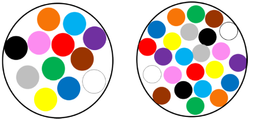
One practice that can make cable dimensions even smaller is to put more fibers in a given tube. For example, the figure below illustrates that 24 fibers with a 200 micron coating dimension occupy approximately the same amount of space as 12 conventional fibers. In fact the packing density is slightly higher in the case with 200 micron coated fibers, but microbending effects can be minimised by using a G.657 Fiber with a microbend-resistant coating. Using this scheme, the fiber count for a given cable design can be doubled.
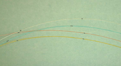
There remains one challenge with this approach: beyond 18 colours, it becomes difficult to distinguish fibers by colour alone. Thus a new approach is required for fiber identification. One option is marking fibers. Key requirements for these marks are that the marks must be visible initially as well as after aging and the marks must not disappear during standard processing. The picture below shows examples of ring-marked fibers.
Improvements in reliability
Long-term reliability is a key concern with optical networks. When building an optical network, the actual cost of cable and passive components represents a relatively small amount of the overall investment (typically less than 20 per cent). The cost of the installation of the optical cable is much more significant and greatly affects the overall deployment budget. The payback on that investment is often greater than 10 years. In order to make the investment worthwhile, the deployed optical fiber must operate properly for the expected lifetime of the network, supporting possible future network upgrades.
Reliability is the measure of how well the cable stands the test of time. There are two types of reliability that are considered with optical networks: optical reliability and mechanical reliability.
Optical reliability requires that there is a useable optical signal after the system is deployed and that performance will be maintained for the life of the network. Tests such as long-term aging of optical cables, crush tests and temperature cycling are used to evaluate long-term optical performance. OFS has been a leader in providing a reliable optical link with several innovations that help preserve optical reliability:
- AllWave zero water peak fiber helps ensure that the attenuation is both low and stable
- AllWave FLEX and FLEX+ fibers provide excellent microbend and macrobend performance to help ensure that temperature changes and cable movement do notimpact system performance
- OFS’ D-LUX® Ultra coating provides excellent durability and microbendperformance
- The AllWave fiber family provides excellent PMD properties to help ensure that the fiber is not only ready for current transmission strategies but for next-generation systems as well.
The second type of reliability is mechanical reliability. This is a measure of whether the fiber will physically break. Optical fiber is very strong, with an intrinsic strength greater than 500 kpsi, but it can have flaws that are distributed throughout its length. Methods for estimating the long-term mechanical performance for optical fiber are well documented in ISO/IEC TR 62048 Power Law Reliability. Key parameters that need to be preserved are proof test strength, dynamic fatigue coefficient (n-value) and the tensile strength of the glass both initially as well as after aging of samples. As stated earlier, optical fiber is strong but the surface of the fiber can easily be damaged by the environment. Therefore, the coating layer and how it adheres to the fiber help ensure that the mechanical integrity of the fiber is preserved.
Optical fibers with 125 micron glass and a 250 micron coating have been deployed for over 30 years. Time has shown that the 62.5 micron acrylate coating layer is sufficient to preserve the fiber in excess of 30 years. These 200 micron coatings have been shown to provide similar performance and as a result are being deployed by several service providers.
Reliability of 200 micron coating
Since optical fibers were first deployed more than 30 years ago, considerable advancements in fiber quality have been achieved. The quartz used to fabricate the bulk of the fiber, which originally was natural material, now is high-purity synthetic material. The quality of the polymers has also improved, providing a significantly better product than that produced 30 years ago. Many of the fibers that were deployed in the 1980s are still in operation today. With the improvements in materials our reliability tests indicate that OFS 200 micron coated fiber is capable of surviving 30 years in the field as well. OFS has tested and shown compliance for our 200 micron coated AllWave FLEX fiber and AllWave FLEX+ fiber to the full set of fiber tests in section 4 of Telcordia GR20.
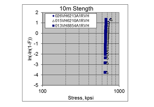
For example, fiber tensile strength has been measured on both aged and un-aged fiber and is consistently well above 600 kpsi. Perhaps more revealing is 10 m gauge length axial strength tests are performed. The figure below clearly shows that the 200 micron coated fiber has high strength when tested under these stringent conditions.
We have also tested dynamic fatigue for the 200 micron coated fiber using the more stringent axial strain method and our data consistently yields nd>20 for both un-aged and aged samples.
Summary
Single-mode optical fiber is now available with an alternate coating dimension of 200 microns. This smaller coating dimension is compatible with the embedded base of fibers and provides 46 per cent smaller fibers that can be used to reduce the diameter of microcables. These fibers prove a new and reliable solution to address the challenge of deploying high fiber count optical cables in crowded ducts.