
Over the past several years, cable operators have seen their networks transform into the premier platform for transmission of data services, both for residential and business customers. In order to accommodate the growth of services and transmission speeds, the networks have been divided into smaller and smaller clusters of customers forming independent service groups.
When fibre came into widespread use in cable television, it was common for one node to serve a cascade of several trunk amplifiers, with each amplifier feeding dozens of line extenders before the RF signals would finally arrive at a customer. That architecture could involve thousands of homes per node. Today, most nodes serve about 500 homes passed and do so via line-extender amplifiers only.
Future-ready
In order to be ready for the near future, these nodes are being sub-divided into smaller service groups, typically feeding 125 or fewer homes each. These smaller numbers allow for gigabit services to be delivered effectively along with legacy video services.
Looking towards the longer-term future, fibre to the home (FTTH) options will demand even smaller service groups, typically 32 or 64 homes each.
With all of these architectures having one thing in common – the need for fibre transmission paths between the headend and service group – let’s take a look at the access network choices and technologies available to help deliver gigabit services.
Supporting a fibre-deep network
Initial system design, and how demands have been addressed to date, are two key areas in assessing how many fibres are available to serve a collection of service groups. Take, for example, a typical Node+3 HFC (Hybrid Fibre-Coax) system designed for 500 homes per node in the early 2000s (Figure 1). Since fibre cable at that time was bundled in buffer tubes or binders of six fibres each, many systems designed six fibres per node. Matching the nodes to the buffers made splicing and organising the fibres easier. Each node would require one fibre for downstream, and one for upstream, leaving four fibres for spares. Business services may have used two more fibres for upstream and downstream dedicated fibre service to a business location, or perhaps all four to feed a ring. Preferably, the ring would involve only two fibres from any single node location for route diversity.
If a node split was required, any spare fibres available could be used, however a 4x4 split requires more than that. We need four service groups where there was just one.
To solve this, 1310/1550nm WDM, coarse wavelength division multiplexing (CWDM) or dense wavelength division multiplexing (DWDM) techniques were, and still continue to be, employed.
A single spare fibre could be used to replace the fibre feed to four or more service groups.
Divide further
With passive analogue techniques, this method worked well enough to do the job. But, what happens when we want to divide further, as would be required for a Node+0 design, or to consider a PON for FTTH? In this case, there may not be enough fibre from the headend to the aggregation point to do the job.
PON requires a single dedicated fibre from the optical line terminal (OLT) to the splitter for each service group. In a true all-passive-plant PON, the OLT is located at the headend; we would need a fibre from that headend out to each splitter location. The required fibre count leaving the headend could be in the thousands. In addition, the loss budget required to feed the splitters might also require a maximum 16-way split, rather than the usual 32, further increasing the count.
Asking this infrastructure to support a new fibre-deep architecture may be asking too much, but what about DWDM, both conventional and coherent (recently developed by CableLabs)?
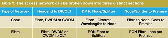
As an example, let us take the above Node+3 system and attempt to convert it into a Node+0 system, and also a PON system. The access network can be broken down into three distinct sections: Headend to Distribution Point (DP); DP to Node or OLT; and Node or OLT to Premise.
When faced with insufficient fibres to feed the aggregation point, the only option was to overlay more fibre cables from the headend out. Now there are more options, and regardless of the option chosen, we want to make certain that we do not have to face this choice again in the future.
Let us examine what happens when we convert a Node+3 system into a Node+0 system (Figure 2). Each former Line Extender location becomes a new mini-Node location. There are other options to reduce the node count, such as employing high-output nodes and reversing the tap strings in the coax, but these methods only have a slight effect in the overall node count while increasing the length of service outages involved in the conversion.
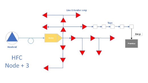
Figure 1
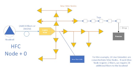
Figure 2
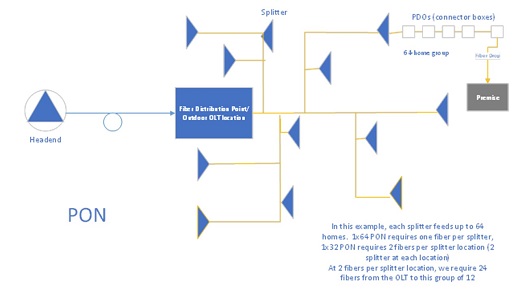
Figure 3
Overcoming challenges
What if we create a PON network from the former node location instead? Figure 3 shows that the neighbourhoods previously served by a line extender are now served by a splitter location instead. By remoting the OLT to this distribution point, we can overcome the fibre shortage and loss budget problems mentioned above.
If we compare the diagrams for these two network options, it is apparent that the required fibre counts are very similar, but the total sheath distance of fibre required is different because only the FTTH network requires installation of new fibre cable beyond the node/splitter location.
In addition, the FTTH network will require drop cables from the plant to each home.
Another important consideration is fibre availability for business services. In a primarily residential network, many business services can ride the same coax or PON network used to serve homes. In some cases, however, the operator may require more. A business might demand their own dedicated fibre for security purposes, or for an unusually high bandwidth demand.
They might require a wholly different architecture, such as a ring, for route protection. For this reason, no matter what the required count for serving residential requirements, there should be extra fibres installed for future business services. The amount will depend upon the commercial density of the particular geographic area.
When it comes to cellular networks and upcoming 5G, these networks traditionally use fibre, but with very small cell sizes, a Coax or PON network could accommodate the required bandwidth. Some Radio Access Networks (RAN) work with dark fibre connecting several radio heads to a common controller.
The bottom line is extra fibre strands should be planned to accommodate any future requirements.
A future-ready network
Ultimately, the architecture required to build advanced networks is remarkably similar between PON/FTTH and HFC Node+0. We can build lots of ‘transport’ plant to feed these fibre distribution clusters, or we can make prudent use of active and passive solutions, including Remote OLTs and DWDM, in order to keep the construction of new fibre cable to a minimum.
By analysing the financial implications of the various options, an operator can decide the best choice for their particular situation and be prepared for bandwidth demands that the future will bring.
Vanesa Diaz is market development manager EMEA at Corning Optical Communications