Unbeknown to most people, the erbium-doped fibre amplifier (EDFA) is a superhero that keeps the world talking and communicating. But almost three decades after its invention, it is struggling to do the job alone.
‘The internet wouldn’t exist without EDFAs,’ stressed Nick Doran, from Aston University, UK. The world was ‘lucky that there were readily available amplifiers’ to boost optical communication signals in the right wavelength range, he says. In that range, we encode signals onto light beams whose colours are least susceptible to losses as the glass fibres they travel through absorb and scatter light. Yet still, the signals eventually grow faint, and so EDFAs boost them when necessary. ‘Without EDFAs we would be lost,’ Doran says. ‘But now, the next generation expects even more bandwidth, so we have to go beyond EDFAs.’
There are many strategies for keeping data flowing, and avoiding a ‘capacity crunch’, Doran underlined. Different fibre types and encoding technologies, such as spatial multiplexing, boost spectral efficiency – the speed with which data can be transmitted over a given bandwidth. They do this by improving the optical signal-to-noise ratio (OSNR) of transmission, but a logarithmic physical relationship means that large OSNR improvements give only small spectral efficiency gains. By contrast, ‘if we double the bandwidth of our amplifiers we double the bandwidth of all systems,’ Doran stressed. That is a ‘factor of two or three’ more effective in increasing data flow, he adds. Therefore, researchers are seeking a new generation of amplifiers to help – or even replace – EDFAs.
A hybrid solution
But they won’t be retiring just yet. EDFAs have excellent amplification properties in the C-band from 1530nm-1565nm, observed Wayne Pelouch, vice president of photonics at Xtera in Allen, Texas. ‘Supplementing the EDFA with other amplification technologies can provide a better hybrid solution for many applications,’ he says. To provide a solution that can be industrialised, Xtera is therefore combining EDFAs with another existing technology, distributed Raman amplification, working together with University College London (UCL).
In March 2018, the collaboration announced a hybrid EDFA/Distributed Raman Amplifier achieving record-breaking 120Tb/s capacity on a single fibre. The demonstration covered nine 70km spans, transmitting wavelengths from 1525nm-1615nm, covering the C-band and L-band. ‘Raman amplification provides both extended wavelength range and improved noise figure (NF), with relatively few additional optical components,’ Pelouch observed. ‘It is optimal for standard effective area (Aeff) fibre, which is less expensive. Very long fibre spans, for example 160km, can be supported within the C-band over 3,000km, or wide spectral bandwidth of 90nm can be supported at shorter 80km spans with high spectral efficiency over transatlantic distances.’
Raman amplification exploits how light very occasionally excites molecules in a fibre to a higher energy state. The molecules relax to their original state by releasing both vibrational energy and light. Because some energy is released as vibration, emitted light has less energy than the previously absorbed light, and is therefore a different colour. In silica fibre, the light wavelength emitted is around 100nm longer, and consequently a 1450nm pump laser can interact with and amplify a 1550nm signal. But, crucially, this also works at other wavelengths.
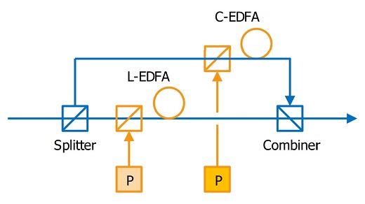
Figure 1: A simplified schematic of C+L. Credit: Xtera
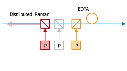
Figure 2: A simplified schematic of C+L hybrid EDFA/Distributed Raman Amplifier. Credit: Xtera
Non-linear thinking
Distributed amplification exploits this effect that occurs continuously within fibre, as opposed to lumped amplification at the end of each span. Compensating for losses in the fibre span, the Raman noise factor is lower than it would be for the same span with an EDFA, Pelouch explained. ‘Distributed Raman improves the OSNR, allowing longer transmission distances and/or higher spectral efficiency,’ he says. Yet Raman amplification is less commonly used than EDFAs, because it needs higher power pump lasers to generate the desired gain at the signal wavelengths. This consumes more electrical power and increases the risk of damage to optical connectors and components outside a controlled environment. Sufficiently high powers can also change the fibre’s refractive index through the Kerr effect.
‘Both Raman gain and the Kerr effect are nonlinear processes that scale proportional to 1/ Aeff of the fibre,’ Pelouch explained. ‘The power-dependent Kerr effect limits the optical transmit power such that the benefits of increasing OSNR with increasing transmit power are balanced versus the nonlinear penalties, which also increase with increasing transmit power. This is true for all transmission systems.’ Consequently, in a hybrid Raman/ EDFA design, the main trade-off is between fibre area and spectral efficiency, he said. ‘Standard 80μm2 Aeff fibres tend to be a good balance,’ Pelouch said. ‘Our hybrid Raman/ EDFA amplifiers are designed for a 25-year lifetime, which would not be possible if there was any significant risk of damage in our submarine line system. The reason is that it is a controlled environment. Also, the Raman power does not cause a Kerr effect for the signals, except under special circumstances of four-wave mixing, which is easily avoided by design.’
Prime the pump
Adding an extra Raman pump, compared to the hybrid Raman-EDFA design, increases bandwidth and OSNR. ‘We can add one pump wavelength to scale the bandwidth within the same basic optical design, without the need for a parallel amplifier,’ said Pelouch. ‘In fact, we only need to add one pump and one optical filter to implement this, relative to the previous design. Therefore, there are savings in both optical component count and space, which makes it an efficient design per bandwidth.’
Paul Harper and his Aston University team has started looking to exploit Raman amplification alone in a lumped, rather than distributed, format. Typically, discrete lumped Raman amplifiers use separate highly nonlinear fibres as the gain medium, rather than the transmission fibre, to ensure adequate Raman scattering. ‘You reduce the pump power required,’ Harper explained. ‘The downside of using highly non-linear fibre is that they have all these other non-linear effects,’ he observed. That imposes an approximately 10-15dB upper limit on the gain attainable.
The Aston team therefore reduces nonlinear penalties through a ‘dual stage’ approach. The first stage consists of 10km of non-linear inverse dispersion fibre (IDF) and provides 14.5dB gain. A 10km singlemode fibre (SMF) second stage adds 5dB gain with minimum additional nonlinear penalty. Such an approach is unlikely to replace EDFAs in the C-band, Harper admits. Instead, it will likely target the O-band, E-band and S-band low-loss windows, from 1260nm-1360nm, 1360nm-1460nm and 1460nm-1530nm respectively.
Banding together
Similarly, Antonio Napoli, a project leader at transmission technology system vendor, Coriant in Munich, Germany, said that his company doesn’t plan to replace EDFAs in the C-band. Coriant also intends to limit Raman amplification to where it’s strictly required.
‘Under certain conditions Raman improves system performance, but might be costly and require higher power than lumped amplifiers,’ Napoli explained. ‘Therefore its usage should be pondered case-by-case.’ Instead, Coriant and its partners are planning to re-design the EDFA in the L-band from 1565nm-1625nm bandwidth, extending the current upper limit of 1615nm by 10nm. However, the company is also entering the O-, E- and S-bands.
‘Coriant is actively working with several industrial and academic partners on multiband systems as a whole,’ Napoli told Fibre Systems. ‘As a first step, we have prepared a testbed with (C + L)-band systems, to be used, for example, to validate the first theoretical results over the (C + L)-band. The main part of our future work will be to define the most cost-effective solutions for O, E and S-bands in terms of amplifiers, but also for what concerns other devices like filters and the transmission techniques.’ Napoli envisages that solutions involving in-line devices, such as optical amplifiers, should enable a modular approach, so customers can follow a ‘pay-as-you-grow’ model, lighting additional bands as needed.
Currently, Coriant is working with its partners to obtain the first results on wide spectrum transmission modelling. ‘The next steps will be on the wide-band component design and network management,’ Napoli said. Coriant conjectures that 200Tb/s in metro areas and 150Tb/s in the longer haul could be realistic targets. ‘We are ramping up to say, OK, these are the possible capacities and the possible scenarios given these values and amplifiers in these bands,’ he said. ‘Our numbers might be conservative. In the metro area, to interconnect data centres, the capacity could be larger.’
An example of what’s possible comes courtesy of Lawrence Livermore National Laboratory (LLNL) in California. Researchers stumbled onto potential E-band amplifier technology when working on neodymiumdoped optical-fibre lasers, which lase at 1330nm, 1064nm and 920nm. They were designing a microstructured optical fibre to suppress emission at 1064nm and amplify 920nm emission, said Jay Dawson, deputy programme director at LLNL. ‘There was spontaneous amplified emission at 1440nm,’ he said. ‘Recognising that was unusual, we took it on.’
Having previously worked in optical communications before taking on his current, defence-focussed role, Dawson recalled that previous attempts to produce amplifiers at this wavelength had faced big problems. In the 1980s, excited-state absorption in the 1330nm region had increased fibre loss when pump light was applied, severely limiting gain. ‘We got 20dB and 1W in an initial cladding pumped amplifier,’ Dawson underlined. However, this initial result was a high power fibre-laser result, not a telecom compatible amplifier.
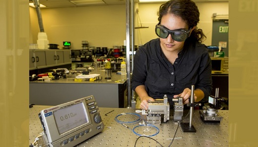
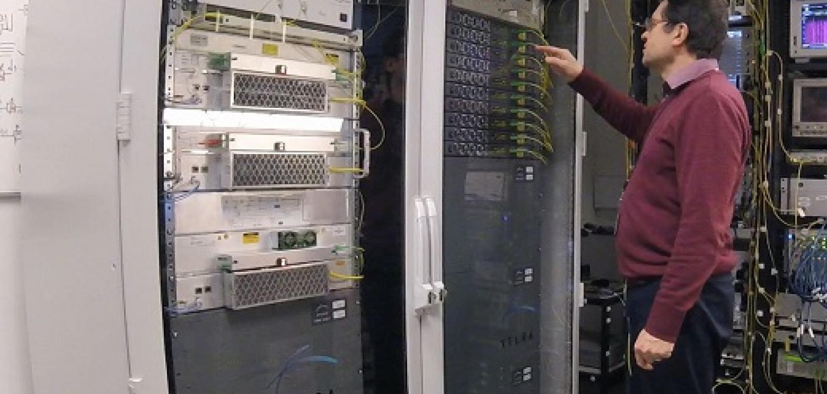
NIF & Photon Science postdoctoral researcher Leily Kiani tests a new optical fibre that could double the bandwidth of fibre-optic cables. Credit: Jason Laurea
Everything to gain
The LLNL team therefore designed a novel neodymium-doped microstructured optical fibre to use in a telecom amplifier, tailored to preferentially enhance E-band optical signal gain. The fibre’s graded index inclusions direct wavelengths from 850nm-1150nm into surrounding cladding, Dawson explained. While excited-state absorption still prevents amplification at 1330nm, the approach can address the 1390nm to 1460nm range.
The resulting neodymium-doped fibre amplifier is intentionally designed so that telecoms companies are comfortable with it. It could also at least double the proportion of light illuminating the low-loss window in glass fibre if commercialised. ‘I look at this and think it’s got the potential to have the form, fit and function of an EDFA and feel very similar to it in another band,’ Dawson says. ‘The work we’ve done has shown that we can get neodymium to open up more bandwidth.’ However, LLNL’s defence focus means that it has little capacity to devote to support further NDFA development, and Dawson would welcome interest from other groups. ‘We’d be very happy to collaborate,’ he says, referring interested parties to LLNL’s Innovation and Partnerships Office.
While such approaches work alongside EDFAs, Aston’s Nick Doran is working on a technology that could replace it, known as parametric amplification. ‘We can anticipate very wide gain regions of maybe four times a standard EDFA,’ he said. Parametric amplifiers contain highly non-linear undoped silica fibres, with very small cores, in order to exploit four-wave mixing, a standard non-linearity in optical fibres that limits transmission capacity. Aston researchers use this to combine a high-power pump laser and the signals that they want to amplify, outputting higher power signals. ‘There’s no energy lost and we can get 0db noise figures,’ Doran explains. However, he added that the ‘revolution, where they replace EDFAs, is some way down the line’.
Two fibre stages
The revolution will require parametric amplifiers to eliminate their current intrinsic sensitivity to polarisation. With optical communication today exploiting polarised multiplexed signals, a parametric amplifier must amplify all polarisations equally – but until recently, they didn’t. The Aston team therefore tried separating the pump beam into two polarised components that enter the amplifying fibre loop in opposite directions.
‘We find that when we do high gain that doesn’t work, because of a stimulated Brillouin scattering interaction between the components,’ Doran said. They now use two fibre stages, one for the anticlockwise component, and one for the clockwise one. ‘That has eliminated polarisation issues,’ Doran said, enabling 15dB amplification from 1532nm-1550nm in a 4x75km system with 1.3dB OSNR penalty.
All these new device designs show the desire to expand what’s currently available. ‘It’s unthinkable that in 10 years’ time the only amplifiers we’ll have will be EDFAs,’ Doran says. But while the communications industry is currently working with what it knows, he thinks EDFAs’ days are numbered. ‘EDFAs themselves have gone as far as they can,’ Doran observed. ‘I would think it would be surprising if there isn’t a replacement.’
Andy Extance is a science writer based in Exeter, UK
Main image credit: Xtera