Data Centre Applications Reference Guide - Networking & Storage
1. Introduction
The definition of the most dominant networking & storage applications in data centers used in this technical paper is derived from the following graphic (source: Cisco):
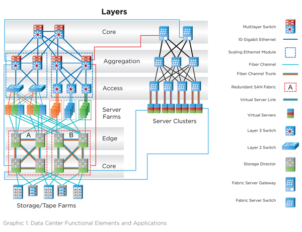
The applications can be grouped into:
Application Functional element
Ethernet Networking area (red marked)
Fiber channel Storage area (yellow marked)
Infiniband High Performance server Cluster and Storage (blue marked)
Note: IP convergence is becoming more and more popular in DCs, resulting in deployment of FibreChannel over Ethernet (FCoE) and Infiniband over Ethernet (IoE) applications. Although they are not listed here, they will be covered in latter chapters.
2. Data Center Cabling Standard ISO/IEC 24764
This standard has been released in April 2014 (ed 1.1) and defines, together with the ISO/IEC 11801 (ed. 2.2 - Generic Cabling for Customer Premises; released in June 2011), the cabling systems for copper and fiber applications in data centers. These standards are used in this paper as reference for linking the mentioned data center applications to standard compliant cabling systems.
2.1 Copper cabling systems
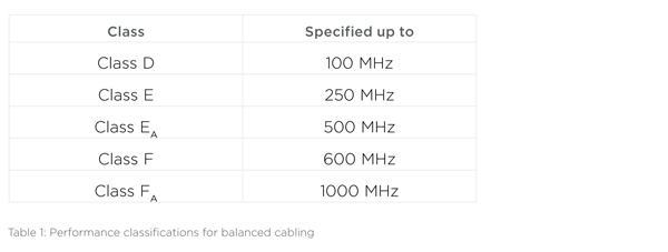
ISO/IEC 11801 ed. 2.2 defines the following performance classifications for balanced cabling:
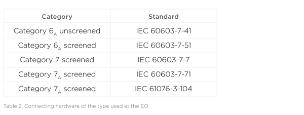
The following copper connector definitions have been made for the equipment outlet (EQ):
2.2. Fiber optic cabling systems
For multimode fiber optic cabling systems, the following cabled fiber definitions are used:
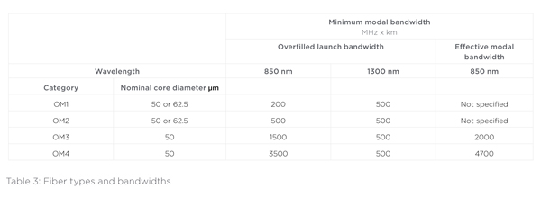
Note: Modal bandwidth requirements apply to the optical fiber used to produce the relevant cabled optical fiber category, and are assured by the parameters and test methods specified in IEC 60793-2-10.
The following fiber connector definitions have been made for the equipment outlet (EO):
• For the termination of one or two single-mode optical fibers the interface shall be IEC 61754-20 (the LC interface).
• For the termination of one or two multimode optical fibers, the interface shall be IEC 61754-20 (the LC interface).
• For the termination of more than two optical fibers, the interface shall be IEC 61754-7 (the MPO interface).
2.3. Minimum requirements for data center cabling
In order to ensure a future proof selection of the data center cabling systems, ISO/IEC 24764 specifies minimum cabling performance requirements for data centers as follows:
2.3.1 Balanced cabling
The main distribution cabling shall be designed to provide a minimum of Class EA channel performance as specified in ISO/IEC 11801.
2.3.2 Optical fiber cabling
Where multimode optical fiber is used, the main distribution and zone distribution cabling shall provide channel performance as specified in ISO/IEC 11801 using a minimum of Category OM3.
Note: The scope of the cabling standard ends at a channel length of 2000m. Lengths in this document that are longer than 2000m are taken from the application standard.
3. Ethernet (IEEE 802.3)
Ethernet applications according to IEEE 802.3 are dominating the networking area in today’s data centers. The server farms in the equipment distribution areas (access) use 1 Gigabit Ethernet (with 10 Gigabit Ethernet knocking at the door). In the aggregation and core areas, 10 Gigabit Ethernet using fiber optic cabling is the choice of cabling designers all over the globe. In mid 2010, the newest IEEE 802.3 has arrived: 40/100 Gigabit Ethernet.
3.1 Gigabit Ethernet over fiber (IEEE 802.3z)
There are 2 main data center applications: 1000BASE-SX and 1000BASE-LX.
3.1.1 1000BASE-SX
1000BASE-SX is a fiber optic gigabit Ethernet standard for operation over 2 multimode fibers using a 770 to 860 nanometer, near infrared light wavelength. This standard is highly popular for intra-building links in large office buildings, co-location facilities, data centers and carrier neutral internet exchanges.
3.1.2 1000BASE-LX
1000BASE-LX is a fiber optic gigabit Ethernet standard using a long wavelength laser (1270 to 1355nm). The application can be run on either two multimode or singlemode fibers.

As mentioned in 2.3.2, the minimum requirement defined by the data center cabling standard for cabled optical fiber in data centers is OM3. Other fiber types are listed for reference only.
3.2. Gigabit Ethernet over copper
1000BASE-T (also known as IEEE 802.3ab) is a standard for gigabit Ethernet over copper wiring.
Each 1000BASE-T network segment can be a maximum length of 100 meters and must offer a Class D channel performance as a minimum. 1000BASE-T requires all four pairs for transmission.
As mentioned in 2.3.1, the minimum performance class requirement defined by the data center cabling standard for copper cabling systems is Class EA which is backward compatible to the Class D performance.
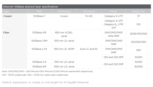
3.3. 10 Gigabit Ethernet
3.3.1. 10 Gigabit Ethernet over fiber
In 2002, 10GBE over fiber has been specified by IEEE 802.3ae with both WAN and LAN application focus. Because of the severe link length limitations of this application when using traditional 50/125 μm (OM2) and 62.5/125 μm (OM1) fibers, the international cabling standards had to define a new laser optimized 50/125 μm fiber (OM3) featuring a much more precise fiber core index profile. The much higher effective modal bandwidth of that fiber allows longer link lenghts meeting the building requirements.
There are two 10GBE multimode fiber applications used in data centers: 10GBASE-LX4 and 10GBASE-SR. Both are dual fiber applications.
3.3.2. 10 Gigabit Ethernet over copper
10GBE over copper (10GBASE-T), defined as IEEE 802.3an in 2007, was similarily challenging for copper cabling systems as IEEE 802.3ae has been for fiber optic systems. Because of the link lengths limitations for Class E/Cat. 6 UTP systems to 37m, the cabling standards had to define the new cabling performance Class EA which is mentioned in 2.3.1, the minimum cabling requirement in data center cabling. Class EA cabling allows 100m channels for 10GBASE-T.
As mentioned in 2.3.2, the minimum requirement defined by the data center cabling standard for cabled optical fiber in datacenters is OM3. Other fiber types are listed for reference only.
3.4. 40/100 GigaBit Ethernet
As the latest ethernet application, IEEE 802.3ba has been published in mid-2010. The standard defines both data rates (40 GBE and 100 GBE) simultaneously. There are 4 applications that are primarily defined for use in data centers:
- 40GBASE-CR4 100GBASE-CR10
- 40GBASE-SR4 100GBASE-SR10
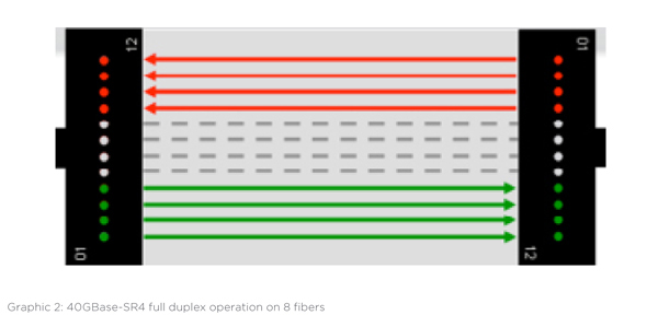
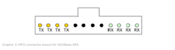
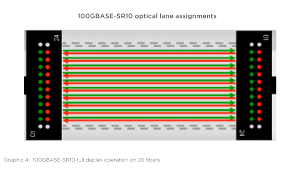
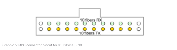
While the -CR variants use a copper cable assembly with limited reach of 7m, the –SR applications are using multimode fiber. 40GBASE-SR4 and 100GBASE-SR10 are the first ethernet applications that require more than 2 fibers for the transmission over multimode fiber. Based on multiple 10 Gb/s data streams in full duplex mode, these applications are built: 40GBASE-SR4 (8 fibers) and 100GBASE-SR10 (20 fibers). Hence, these applications require the use of the multi fiber connector MPO. Although 40/100 GBE multimode applications dominate the data center, the following table also includes singlemode applications in order to give a complete overview about all of the 40/100 GBE applications.
3.4.1. 40GBASE-SR4 (40GBE)
The following graphics illustrate the concept of the parallel data transmission on multi-fiber links using the MPO connector and the respective pinout for 40GBase-SR4 on the connectivity.
3.4.2. 100GBASE-SR10 (100GBE)
The following graphics illustrate the concept of the parallel data transmission on multi-fiber links using the MPO connector and the respective pinout for 100GBase-SR10 on the connectivity.
100GBASE-SR10 optical lane assignments
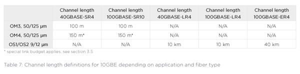
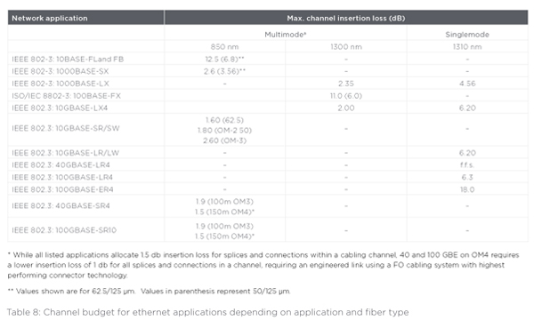
3.5. Channel power budgets for Ethernet applications
In addition to the link length definitions, the power budget definition for cabling systems is another critical parameter to monitor when deploying FO applications. The following table outlines the cabling system power budget for the above mentioned ethernet applications.
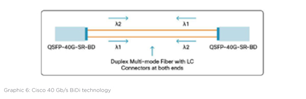
4. Proprietary Cisco 40 Gb/s BiDi
Cisco has developed a proprietary 40 Gb/s technology using 2 fibers. This technology is not compatible with the IEEE standard for 40 Gb/s Ethernet. The Cisco QSFP 40 Gb/s BiDi transceiver has two 20 Gb/s channels, each transmitted and received simultaneously on two wavelengths. The result is an aggregated 40 Gb/s link over 2 fibers, connected with a LC-Duplex connector. The following graphic shows the technology.
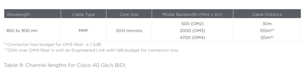
The channel loss budget for 40 Gb/s BiDi is 2 db. This results in the following cabling specifications:
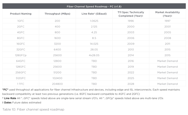
5. Fiber channel applications (INCITS, T11)
Fiber Channel (FC) is a gigabit-speed network technology primarily used for storage networking. Fiber Channel is standardized in the T11 Technical Committee of the InterNational Committee for Information Technology Standards (INCITS), an American National Standards Institute (ANSI)–accredited standards committee. It started primarily in the supercomputer field, but has become the standard connection type for storage area networks (SAN) in data centers
The following shows the FCIA (Fiber Channel Industry Association) technology roadmap for this application:
5.1 Fiber channel overview
5.2. Fiber channel over copper
Although most users link the fiber channel application to transmission over fiber, there are also specifications available to run FC over copper. In 2007, INCITS 435 has been approved containing a set of specifications for the “FC-BaseT “ applications. The rationale behind these copper definitions was the user perception of fiber optic being expensive. With the copper definitions, T11 wanted to improve the fiber channel competitiveness in low cost environments.
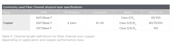
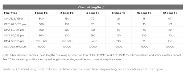
5.3. Fiber channel over fiber
As mentioned in the previous chapter, FC mainly runs on fiber optic cabling systems.
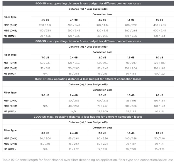
There are several length vs. media definitions depending on the specific fiber channel application to be deployed. The following table provides a complete overview:
5.4. Fiber channel over Ethernet (FCoE)
Fiber channel over Ethernet (FCoE) is a new extension of the fiber channel storage protocol that uses Ethernet as it’s physical transmission technology. FCoE combines fiber channel and Ethernet to provide end users with a “Converged” network option for storage SAN connectivity and LAN traffic. Combined with enhancements to Ethernet, FCoE allows data centers to consolidate their I/O and network infrastructures into a converged network. FCoE is simply a transmission method in which the fiber channel frame is encapsulated into an Ethernet frame at the server. The server encapsulates fiber channel frames into Ethernet frames before sending them over the LAN, and de-encapsulates them when FCoE frames are received. Server input/output (I/O) consolidation combines the network interface card (NIC) and host bus adapter (HBA) cards into a single converged network adapter (CNA). Fiber channel encapsulation requires use of 10-Gigabit Ethernet transmission electronics.
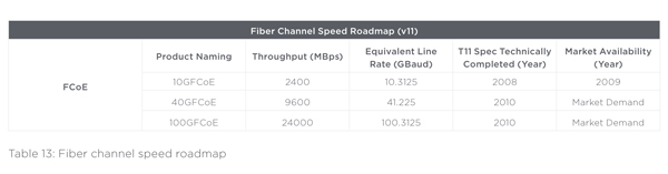
FCoE tunnels FC through Ethernet. For compatibility all FCFs and CNAs are expected to use SFP+ devices, allowing the use of all standard and non standard optical technologies and additionally allowing the use of direct connect cables using the SFP+ electrical interface. FCoE ports otherwise follow Ethernet standards and compatibility guidelines.
5.5. Channel power budgets for FC applications
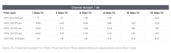
The multimode channel lengths given in 5.3 are based on an allocation of 1,5 dB insertion loss of all connectors and splices within a channel. However, a connector/splice loss in a channel deviating from the 1,5 dB results in different max. channel lengths. The following table gives an overview.
6. InfiniBand
InfiniBand is a technology that was developed to address the performance problems associated with data movement between computer input/output (I/O) devices and associated protocol stack processing. The InfiniBand Architecture (IBA) is an industry-standard architecture for server I/O and inter-server communication. It was developed by the InfiniBand SM Trade Association (IBTA) to provide the levels of reliability, availability, performance, and scalability necessary for present and future server systems - levels significantly better than can be achieved with bus-oriented I/O structures. Although InfiniBand was developed to address I/O performance, InfiniBand is widely deployed within high performance compute (HPC) clusters and storage networks due to the high bandwidth and low latency transport characteristics it offers.
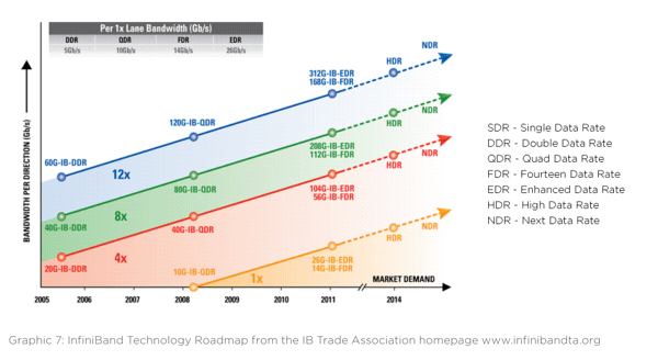
The following graph shows the InfiniBand Roadmap taken from the homepage of the InfiniBand Trade Association www.infinibandta.org.
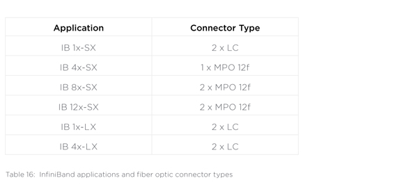
The SDR-application for multimode (IB 1x-SX)and all singlemode applications (IB 1x-LX) use 2 fibers with LC connectors for transmission while all other applications starting with DDR use the multi-fiber MPO connector.
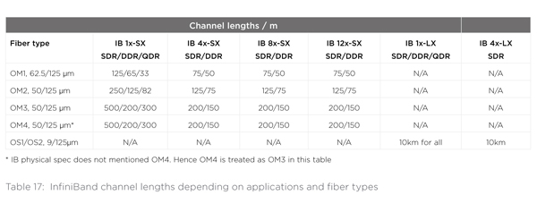
6.1. Channel lengths
The maximum channel length depends on the data rate, the number of parallel lines and the optical fiber type. The following table summarizes this:
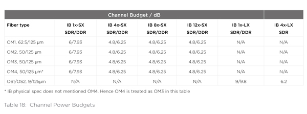
6.2. Channel power budgets for IB applications
TE Connectivity
TE Connectivity is a $13 billion technology company that designs and manufactures the electronic connectors, components and systems inside the products that are changing the world. Our dedication to innovation, collaboration and problem solving helps engineers worldwide solve some of their biggest challenges, so they can create products that are smarter, safer, greener and more connected. Our components are found in almost every product in the world that uses electronics, making us a small part of millions of big ideas.