
One of the chief advantages of optical fibre cables – over those made from copper – is that they are significantly smaller and lighter, so are easier to handle and install. Standard twisted-pair copper cables used for the old telephony trunk networks were enormously heavy, with typical cables measuring between 20 and 40mm in diameter and weighing almost half a tonne per kilometre. And that’s only a 100-pair cable; a 1,000-pair cable would frequently weigh more than three tonnes per kilometre. Installation methods for copper cables were limited, with the majority being physically pulled into the ground or into a main duct.
Being smaller, and therefore more fragile, these new optical fibres forced the telecoms industry to reconsider its installation methods. The earliest optical fibre cables were only of around 100 fibres in count, and weighed about half as much as a 100-pair copper cable. But there was a problem. Optical fibres, although otherwise very durable, are sensitive to the effects of tensile stress – in other words they do not tolerate stretching – as can happen if these cables are simply pulled in. Consequently the weight of first-generation optical cables was mostly taken up with a large strength member, usually made from steel.
As is so often the case, some lateral thinking and a slice of serendipity led to a major breakthrough. While experimenting with small fibre packages that lacked a significant strength member, researchers at British Telecom Research Laboratories in the UK during the early 1980s tied a parachute to the cable end to collect air blown into the duct with the cable – in order to exert a pulling force on the cable. To their surprise, when the parachute came away unintentionally, the lightweight cables continued to install. When they looked into the maths and physics of the phenomenon, it became clear a distributed force was acting along the length of the cable, gently guiding it through the duct. Unlike previous installation methods, which push or pull the cable from one end, the distributed force creates minimal strain or compression. This discovery spelled the start of the air-blown fibre and cable era, which has come to dominate optical fibre installation to this day.
Under pressure
To maximise installation efficiency, and optimise the cost and performance of optical cable, it is useful to understand the parameters involved in the technique. First let’s consider the air pressure. What’s important is not simply the air pressure at the start of the route; rather it’s the change in pressure with distance along the route. This ‘pressure gradient’, generated as high pressure (in the blowing head) and decaying to atmospheric pressure at the route end, propels the cable through the duct. The value of the pressure gradient will depend, on the pressure at the start of the route as well as the length of the route.
The size of the cable and of the duct carrying it are also important, and here things become interesting. It turns out that larger diameter cables are easier to install than smaller ones with the same weight, because the air has a greater contact area with the cable. Also, the larger the duct, the better the installation performance – all other things being equal, which of course they never are. These gains in performance don’t come at zero cost. There is clearly more material in a larger duct so the product cost is higher, and installing the duct will require a larger trench, pushing up the cost of civil works. The final issue is sometimes ignored – with ruinous consequences – and that is the matter of air consumption. Blowing cable is all about pressure, and to maintain pressure in an unnecessarily large duct can require a large and extremely expensive compressor.
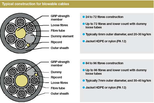
About 300 million kilometres of optical fibre cable were produced in 2014, according to the latest edition of CRU Group’s ‘Optical Fibre and Cable Monitor’. Clearly, it makes no sense for cable makers to produce artificially large diameter cables to benefit blowing and, of course, duct manufacturers have no interest in making the same error. Instead, the industry trend is in the opposite direction, with cable makers looking to squeeze more fibres into increasingly smaller cables (see, for example, Redefining density, Fibre Systems Autumn 2015, pp 25 – 27). Today a typical 96-fibre cable designed for blowing is of the order of 7mm in diameter (rather than 17mm or more for the original pulled type) and installs into a duct of 10mm internal diameter (and not a duct of at least 25mm). Yet at the same time customers are wanting ever longer installation span capabilities, often up to 2km.
The main factors affecting cable installation are the weight of the cable itself and the friction level between the cable and the duct. Cable makers have cut product weights remarkably, from a value of up to 300kg/km for traditional pulled cables to as little as 30kg/km for the lightest 96-fibre blown fibre cables. This improves the installation performance significantly. Three factors have been instrumental in this: (i) The use of smaller, non-metallic strength members; (ii) the ability to use smaller loose tubes in the cable brought about by improved processing and more bend-resistant optical fibre; and (iii) to a small degree the adoption of thinner cable sheaths.
The other factor affecting installation – the friction between duct and cable – has largely been addressed by duct suppliers. Ducts have traditionally been produced from polyvinyl chloride (PVC) or polyethylene. PVC displays relatively high friction for blowing purposes, so has largely been ignored. Polyethylene has superior friction levels, and high-density polyethylene (HDPE) has especially low friction when used in this application. However, to be able to blow cables up to distances of 2km, even low-friction HDPE may not be sufficient, so duct manufacturers have devised different inner layers for their ducts that are optimised for blowing. Essentially they take the form of a low friction ‘liner’ that is bonded to the inside of the duct. The advantage here, compared with changing the whole duct, is that the minimum quantity of additional materials is used, and the outside of the duct does not become slippery which would otherwise affect handling and the ability to joint it.
Further refinements have included the use of anti-static materials in the duct lining that dissipate static build-up, which can otherwise inhibit the installation of very small, typically sub-2mm diameter, so-called ‘fibre units’ (a term now generally used to describe the small fibre packages designed to be blown into small microducts). Although beyond the scope of this article, manufacturers have also worked hard to package ducts into multiples that are easily handled and broken apart where needed; these packages can even be constructed to comply with differing fire regulations and environmental contamination. The duct industry has progressed to the extent that customers have been heard to remark that it is the duct package that is the ‘clever part’ while the optical cable is the commodity item.
Equipment examined
If the cable and duct suppliers are two legs of the proverbial three-legged stool, the producers of cable installation equipment form the third, vital leg. At first sight, the job of the equipment maker is straightforward. Their equipment simply has to move the cable from its transport container (reel or pan) to the duct mouth where the air will carry it away. In reality it’s not quite so simple. High pressure at the entrance of the duct tends to force the cable back out of the duct and onto the ground. So it is necessary to push the cable into the duct entrance and keep pushing until there is sufficient cable inside the duct for the blowing process to take over. This can be achieved with drive wheels or a drive belt. Belts generally perform better with larger stiffer cables and drive wheels are preferred for lighter, more flexible cables. Cable stiffness is itself a tricky issue. Cables need to be stiff enough to be pushed into the duct as far as needed, but not so stiff they resist traversing any bends in the route. Sophisticated machine producers have developed software that uses all the cable parameters, the duct size and friction level to predict how far a cable will install into a given route.
It’s not enough for the equipment supplier merely to provide a belt/wheels and motor, plus an interface to the duct. The apparatus also needs a control mechanism that stops the cable being over-pushed. Excessive pushing will lead to kinking, with potentially fatal results for both the cable and fibre. Modern equipment controls this process by providing a variable push force, with an upper limit that can initially be determined by finding the force needed to buckle the cable – known, rather unfortunately, as ‘crash testing’. In other units a mechanical or optical sensor is used to spot the onset of buckling and adjust the machine controls accordingly. Both methods have their strengths and weaknesses. The ‘crash test’ needs to be performed at the start of each installation, while a buckle sensor is another component that can fail and may be affected by water and temperature.
A further function of the blowing unit is that it needs to guide the cable within the machine and prevent as much air loss as possible by using effective seals. Where machines are designed for a range of cable and duct sizes, then interchangeable sub units for cable and duct fitted are the norm. Unless the user opts for a bottled compressed air supply, the blowing unit also needs to interface to a compressor able to supply sufficient air of the appropriate quality. Systems frequently operate at 10 bar or 15 bar, and vary from portable machines supplying less than 100 litres per minute, to towed compressors capable of generating several cubic metres of air per minute. The choice of pressure and consequent flow rate can also be determined by the same software used to predict a cable installation length.
Air quality can be a parameter that’s all too easily ignored, especially if the user fails to match blowing units and compressors together. Firstly, it’s vital to use air free from the mineral and synthetic oils used to lubricate compressor engines. They can create havoc with duct linings, leading to a rise in friction and a massive drop in installation distance. Compressors need an oil filter and – separately – a means to remove water from the delivered air. Air compressed to 10 or 15 times atmospheric pressure is inherently saturated with water, which tends to condense at the start of the route when the duct is cooler than the compressed air. This is frequently the case so the equipment set also needs an air cooler.
The very first blowing units were individually machined from solid brass and gave rise to the first version used in the field – the BT Unit 1A –introduced in 1986. These machines had no buckle control but were adequate for installing the fibre products in use at the time. From 1994 still smaller fibre products (down to 1.1mm diameter for four fibres) were introduced and a successor machine, the BT 2A with buckle sensing, was brought in during 1997. Since 2000, several machine ranges have come to market, featuring adjustable speed, push force, quick release fittings and the ability to handle cables over a wide range of sizes, from 1mm to approximately 30mm in diameter, and microducts from 3mm diameter to main ducts up to 50mm. The illustrations in this article show some of the equipment in use today.
Conclusion
Air blowing is now a mature technology that has proven itself over the course of several decades. Provided that the correct cable, duct and machine partners are chosen, blowing enables reliable cable deployment with little or no impact on the performance of the optical fibre cables. The advantages of blown fibre over other methods, such as pulling, pushing or direct burial, include faster installation using fewer technicians in the field, as well as the ability to add or replace cables in existing ducts as and when required.
Future advances in air blowing are likely to involve improved materials, both for cable sheaths and duct linings, as well as refinements to suit ever smaller cables – given the industry trend towards increasing density. In future, the emergence of new multi-core fibre types and so-called space division multiplexing (SDM) could shrink cables even further. As the cables become thinner and less robust, the onus will move to equipment makers to protect them further during installation. This may require new control mechanisms that will also produce more intelligent blowing machines, able to adapt more quickly to a wider set of cables. By definition it’s hard to anticipate a ‘eureka’ moment that will see another new technique emerge, but we can be sure equipment makers will never stop looking.
- David Stockton is an independent consultant specialising in optical fibre and cable technologies, who is currently working with Condux on cable installation techniques
