Fibre characterisation has been a part of my career since I joined York Technology in 1983. York had developed the FCm 1000, the first automatic fibre characterisation machine. This mighty machine could measure all of the fibre’s critical parameters, including end face geometry, mode field diameter and refractive index profile, as well as perform optical time-domain reflectometer (OTDR) testing, spectral attenuation measurements and, for multimode fibres, find the modal dispersion.
Weighing in at about 200kg, this monster was firmly aimed at the test and measurement lab in the factory, where there was access to both ends of the fibre under test. It also went into the field. When BT wanted to characterise installed fibres, two BT vans were kitted out with these machines on anti-vibration tables and York worked out how to connect them to do field measurements.

Fast forward about 20 years and a range of field test equipment had become available for the basic tests for installed cabling, including insertion loss, return loss and OTDR testing. However, as data rates climbed to 10Gb/s and boom-time enthusiasm fuelled the prospect of 40Gb/s serial transmission, additional parameters became critical to the performance of installed cabling. Satisfactory losses were not in themselves a guarantee of satisfactory system performance; engineers and technicians also needed to be concerned with the dispersion properties of the link.
Accurate optical dispersion compensation requires precise knowledge of the chromatic dispersion (CD) of the link, especially when considering faster speeds like 40Gb/s. High-speed direct-detection systems also have tight limits on their polarisation mode dispersion (PMD) tolerance. The sometimes chaotic, boom-time deployments and fibre shortages added complications, including a lack of records, uncertainty over fibre types and grades deployed, and fibre of dubious quality being used for some projects, all of which led to a requirement for comprehensive fibre characterisation.
Testing installed cabling
Around this time, Optical Technology Training developed advanced training courses in OTDR, CD and PMD measurements, working with most of the world’s test equipment vendors. We also completed many real-world fibre characterisation projects to support some network operators’ expansion and upgrade plans, and the lighting up of dark fibre routes. When the IEC started writing standards for PMD testing of installed cabling, my expertise was called upon to make sure that the standard was accurate, fair and unbiased.
The ITU also began working on a Recommendation (G.650.3) for testing installed cabling, rather than just testing fibres and cables in a factory. With the support of test equipment vendors and the UK’s ITU-T co-ordination committee, I proposed extensive improvements that were adopted in the 2008 edition of G.650.3. This included, for the first time, a standards-based definition of ‘fibre characterisation’:
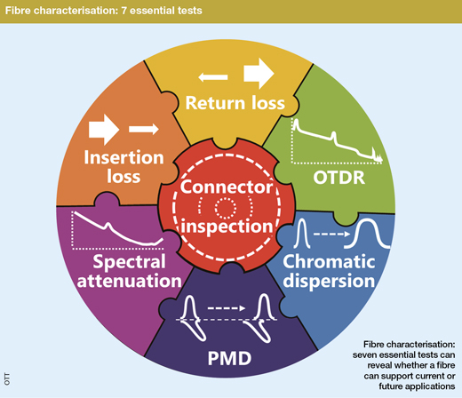
3.2.3 fibre characterisation: A comprehensive suite of measurements that is carried out on an optical fibre cable link to determine the key performance attributes of that link which may affect current or future applications that operate over that link. Fibre characterisation also allows the quality of the optical fibre cable link to be assessed, including the identification of the type and grade of fibre installed. Full fibre characterisation includes connector end face inspection, insertion loss measurements, return loss measurements, OTDR testing, chromatic dispersion testing, polarisation mode dispersion measurement, and spectral attenuation.
This definition of the fibre characterisation process encapsulates two key concepts and required outcomes. First, we should be assessing the ability of the link to support ‘current or future applications’ and second, we should be able to identify the type and grade of fibre. These required outcomes lead to seven required measurements that make it possible to meet those objectives, even if no further information is available about the fibre under test.
Another 10 years on, it is important to consider whether the definition of fibre characterisation is still applicable for modern advanced communication systems that are likely to include coherent transmission, as well as the commercial and contractual requirements in the industry developments. These include:
- coherent transmission systems for 100G+ data rates that use electronic dispersion compensation
- increasing use of complex modulation formats, including PAM4 and n-QAM
- increasing use of Raman amplifiers
- increasing use of dark fibre for data centre interconnect (DCI) and other applications
- the obligation being placed on some incumbent operators by regulators to make dark fibre products available
- potential fibre shortages as global demand for fibre continues to increase
There are many ways in which advanced coherent transmission systems are different to the direct-detection 10Gb/s systems that have served the industry so well. One important aspect is the use of electronic dispersion compensation (EDC) integrated into the sophisticated digital signal processing (DSP) circuitry that is necessary to recover the data in, for example, a 100Gb/s DP-QPSK channel.
The application of EDC means that it is no longer necessary to know the precise total chromatic dispersion of the link in order to perform dispersion compensation. Nevertheless, detailed knowledge of the type of fibre deployed is increasingly important to optimise transmission system design. If the fibre type is not known, then chromatic dispersion measurements are the most effective way of determining this.
EDC does have limits in the amount of chromatic dispersion that can be handled, but this is not currently standardised. Most long-haul systems will have a very high dispersion tolerance. However, a new generation of more cost-effective and lower-power-consumption coherent systems may impose tighter limits that may become critical to overall system performance.
EDC can also usually cope with higher levels of PMD than 10Gb/s direct-detection systems, but again the tolerance of such systems is not unlimited. Also, fibre routes with high PMD installed in dynamic environments such as aerial cable systems, may experience very rapid changes in the state of polarisation (SOP) that can make it difficult for the coherent DSP to keep track of the SOP, a necessary step to recover the data. Several intermittent system failures have been attributed to this phenomenon, with lightning strikes attributed as the most likely cause. This is not thought to be a widespread problem, for network operators using sophisticated DSP operating with the safety net of FEC. But this issue serves as a reminder that fibres with low PMD are going to be more reliable than fibres with high PMD.
Modern high-performance systems at 100Gb/s and above will be using polarisation multiplexing. If the fibre route exhibits significant amounts of polarisation dependent loss (PDL) then again, in theory, this could cause problems for the DSP, particularly in a dynamic environment where changes of SOP would also lead to changes of signal amplitude. So, is it necessary to add PDL to the list of required measurements for fibre characterisation? Not many people have done PDL measurements on installed fibre, but this was obviously a concern for some operators before deploying coherent systems. AT&T, for example did some measurements on a 900km route looped back, including reconfigurable optical add-drop multiplexers (ROADMs) as well as erbium-doped fibre amplifiers (EDFAs) and dispersion compensating modules (DCMs). Overall, the PDL was what would have been expected from the concatenation of the PDL of the network elements alone, and so it can be assumed that the fibre itself makes a negligible contribution. Thus, provided that the PDL of the network elements and the polarisation-dependent gain of the amplifiers is controlled via the specification of those components and subsystems, then network operators shouldn’t have to worry about PDL.
Of course, not everyone is deploying coherent technology – many 10Gb/s direct detection systems are still being deployed – so we recommend applying test limits for the link based on 10Gb/s performance, to give us confidence that 100G coherent will also be supported.
Signal to noise tolerance
As the industry migrates to more complex modulation formats, such as n-QAM for coherent systems designed for going beyond 100Gb/s, this places increasingly tight tolerances on the optical signal to noise ratio (OSNR) of the signal. This OSNR requirement can limit the reach of long-haul transmission systems. Does this factor imply any changes needed to fibre characterisation?
Well, of course one way to get a better OSNR is to make sure that there is a stronger signal getting to the far end, so low loss in cabling infrastructure is always good. This doesn’t really mean that new measurements are needed, but it does become desirable to tighten up the criteria for the amount of loss that is considered acceptable. With some fibre vendors now touting ultra-low loss (ULL) fibre with losses as low as 0.17dB/km, then a reconsideration of acceptance criteria for routes constructed using such fibres is called for, particularly when compared with the very relaxed specification in ITU Recommendations.
For cheaper, non-coherent systems targeted at metro-type distances, PAM4 signalling is now being used to achieve the required throughput without venturing into the coherent domain. This calls for cleaner signals compared with on-off keying, so low loss is again a requirement.
Another way to get better OSNR is to use low-noise amplifiers and this is one of many potential motivations for deploying Raman amplification. However, Raman amplifiers are extremely sensitive to the quality and type of deployed fibre infrastructure. The amount of Raman gain varies significantly with different fibre types, so it is important to identify accurately the type of fibre and, for G.655 fibre types, the precise brand or grade of fibre. If this is not known, then measuring the chromatic dispersion characteristics will allow an expert to identify the fibre type precisely. So, although it may not be necessary to know the amount of chromatic dispersion to carry out compensation, chromatic dispersion measurements may be needed to determine system performance.
Another critical factor in achieving the required amount of Raman gain is to analyse carefully the quality of fibre infrastructure at each end of the fibre link. We need to minimise the number of connections and check their cleanliness and optical performance carefully. This requires skilful use of the OTDR to give high-resolution measurements at each end. It may not be sufficient to test from the outside plant optical distribution frame (ODF), as any poor-quality cabling inside the building between the ODF and the equipment rack can have a disastrous effect on Raman amplifiers.
Some people also say that to more accurately predict the Raman gain, it is useful to know the loss that the Raman pump sources will be experiencing. So, knowledge of losses in the 1450nm region of the optical fibre transmission spectrum might also be useful. Of course, by including spectral attenuation measurements in the fibre characterisation process, you will know the loss at all wavelengths that may be needed for current or future network systems operation.
Commercial considerations
An interesting trend in the industry is the increasing use of dark fibre for applications such as the data centre interconnect (DCI) market. In some territories, the incumbent operator is now being forced by telecoms regulators to make their unlit fibre resource available to others to attach their own equipment, on a dark fibre basis, rather than forcing them to take managed services. Incumbent operators are likely to have a lot of fibre and cable that has been in the ground (or up in the air) for a long time, and may be reaching the end of its intended operational lifetime. So comprehensive fibre characterisation should be a key element of any dark fibre contract to make sure that the infrastructure is still of an acceptable quality.
Most dark fibre contracts run for extended periods; a 10-year contract is not unusual. In a 10-year period it is likely that there may be one or two upgrades of transmission systems. This highlights the importance of the analysis of fibre characterisation test results to support future, as well as current day-one operation of the link. Once the link is operational and carrying live traffic, the operator does not want to take the system out of service, to do more tests on the fibre to see if it is suitable for an upgrade. Much better to find out as much as possible about the dark fibre before it is lit!
Furthermore, it has been quite widely reported that the demand for fibre is outstripping manufacturing capacity, and so this may lead us to a similar situation to that experienced in the telecoms boom time. Some people may be faced with the choice between long waiting times for fibre from reputable, established suppliers and fibre of unknown quality that is immediately available from unknown sources. In these instances, full fibre characterisation can be used to assess the quality of the installed fibre, to make sure that it meets the specifications and is of the type and grade of fibre that it is supposed to be. In many territories, it is quite common for independent third-party fibre characterisation to be conducted on installed cabling as part of the commercial conditions of a major project.
In conclusion, the concept of fibre characterisation has been defined in the ITU G.650.3 Recommendation for nearly 10 years now. There have been a couple of revisions of G.650.3 during that time, but nothing that has changed the fundamental definition of fibre characterisation. There are many motivations for fibre characterisation, requiring the full suite of tests or in some cases a subset of those tests. Not all motivations are technical, there are commercial and contractual reasons too. Thus, fibre characterisation remains a key part of many projects, particularly dark fibre projects, and it is important that people involved with the process are competent to perform measurements, ensure the validity of test results and analyse the results so that they are able to report on infrastructure quality and the ability of the link to support current and future transmission technologies.
• Richard Ednay is technical director, Optical Technology Training Ltd and chairman of the BSI committees on fibre optic and fibre optic systems. For many years he has been the UK’s principal expert on testing fibre optic cabling, responsible for the UK’s input to IEC standards and project leader for some of those standards. He has also participated in ISO/IEC, ITU-T and TIA standard groups. He is responsible for the Certified Fibre Characterisation Engineer programme, available from OTT’s training delivery partners around the world. www.fibrecharacterisation.com.