Introduction
Data Center Interconnect is driving optical innovation. Component suppliers and systems vendors are racing to offer the highest data rate, longest reach and least expensive optics for use within and between data centers. The innovation in speed, packaging, digital signal processing and systems is enabling new applications for data center operators. This article describes some of the innovative ways data centers are using these new options in optical transport for data center interconnect.
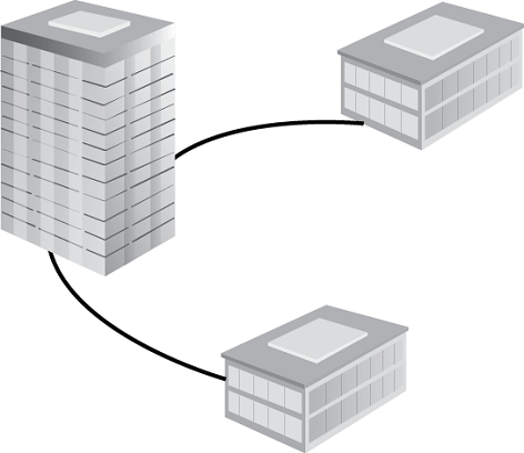
Peering PoP Offload
Problem: Many data centers are located in urban centers where the costs for real estate, rack space, electricity, cooling, cross-connect, labor and other charges can be high. When additional data center resources are needed these costs can be prohibitive or the resources may be unavailable altogether.
Solution: Find a building to house the data center in more distant locations where these cost are lower and then connect the remote location to the urban data center using dark fiber and DWDM.
Benefit: This provides more space for servers, storage and applications at lower operational costs. Energy for cooling can be minimized through site locations that use natural cooling and hydroelectric power generation can provide a clean energy source.
Description: Using dark fiber and DWDM to create an optical link from a remote data center to the core data centers can have an ROI of less than one year compared to buying a comparable lit service. One fiber is capable of supporting many wavelengths, even running at 100G and a typical optical chassis can support terabits of data throughput - more than enough for most data center interconnect scenarios.
100G Access
Problem: One customer needs 100G access to the data center or many customers from similar locations need 10G access to the data center. Fiber is available but there may be limitations on the wavelengths available on the DWDM network.
Solution: Use a 100G CPE that can support one customer at 100G or aggregate many customers at 10G onto any single 100G wavelength of the ITU grid.
Benefit: Customers get the data center access they need and the data center gets new revenues while preserving optical spectrum using only one wavelength.
Description: 100G optics are the fastest growing port type according to analysts Ovum and IHS Infonetics. Rapid decreases in size and cost are enabling 100G data rates in switches and routers and in optical transport between data centers. Rapid innovation is introducing a number of standards, MSAs and proprietary approaches into this technology. Coherent CFP2 100G optics are compact and low power. They offer spectrum efficiency because they use only one wavelength at 100G. In addition, they can reach up to 1,200km without the need for amplification.
Parallel optics that use 4 wavelengths of 28G each to deliver 100G are becoming the preferred within the data center. Certain varieties of these QSFP28 optics can also be used on dark fiber within a DWDM wavelength plan using ITU grid wavelengths.
Using either of these optical technologies in a Network Interface Device (NID) enables a service provider to create a single 100G link between the customer premises and the POP. If the NID is a simple optical demarcation device, then one customer can receive the full 100G bandwidth. With a switching CE 2.0 NID a number of 10G customers can share the 100G bandwidth.
Low Latency Interconnect
Problem: Some applications require extremely fast response time (low latency) to perform correctly. In order to get the required performance from the network, latency must be reduced from each network element and process.
Solution: Faster response time can be achieved by using these optical design criteria: 1) use an optical transport solution that has low latency components and low overall systems latency, 2) design the network for low latency by following low latency design rules, and 3) keep the fiber distances as short as possible.
Benefit: These three strategies will minimize latency in the optical transport and in conjunction with low latency servers, storage, and applications, will create the lowest latency platform for any application.
Description: Latency optimized optical systems will minimize the latency introduced in the transport network. There a few key factors to consider when creating low latency optical networks, these include:
- Distance - The best way to minimize transport latency is to have the shortest fiber connection from the computing platform to the user.
- Data Rate - Most fiber networks are built using Dense Wave Division Multiplexing (DWDM). DWDM is capable of supporting all data rates and protocols. Therefore, build a network with the fastest data rate available as the first step to a low latency optical network. Today, that means 100G links. However, not all 100G components have the same latency. When moving to 100G it is important to understand the latency from the Transmit side of the link to the Receive side of the link. This measurement will reveal the latency in this component. The latency range for 100G modules today ranges from about 300 nanoseconds to about 8 microseconds.
- Dispersion Compensation Fiber or Modules - Chromatic dispersion is a broadening of the input signal as it travels down the length of the fiber. The farther the signal travels, the more dispersion is introduced. A number of competing dispersion compensating technologies exist for use on the majority of fiber installed around the world. The best dispersion compensating components introduce a negligible 0.15 nanoseconds of latency per kilometer.
- Passive Optical MUX/DEMUX - Optical multiplexing enables the addition or extraction of individual wavelengths so they can serve specific locations where bandwidth is needed. There are many vendors of MUX/DEMUX equipment and a number of technologies used to add and drop signals. The bandpass and insertion loss characteristics of passive optical the mux/demux can influence what other components are required and by requiring less efficient dispersion compensation or amplification, can have an effect on the overall latency.
- 100G Transponders - 100G ports will soon be the preferred data rate for most new optical transport links between data centers. There are a number of 100G technologies coming to market. Some offer longer reach, some offer lower cost and some are optimized for latency. Direct detect transparent transponders should be used when low latency is required on 100G links.
Disaster Recovery
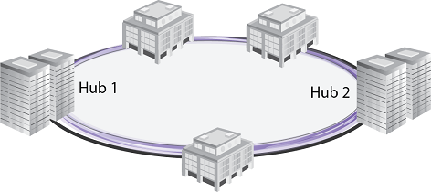
Problem: Critical information stored at a data center must be replicated and stored at a separate location to ensure business continuity or to meet regulatory requirements. A similar application is the real-time synchronization of data bases operating in different locations but connected by optical fiber.
Solution: Create an optical transport link to the remote data center to replicate the mission critical data. Latency can be determined by adding the sum of the fiber latency to the sum of the latency through any optical components in the transport network to calculate the overall latency of the link. To keep data bases synchronized and reduce file transfer time use the highest data rate transponders and the lowest latency components on the shortest possible fiber links.
Benefit: Ensures that an enterprise can function even in the event of a catastrophic failure of one data center and meets regulatory requirements for financial and insurance purposes. For data synchronization that is required for disaster recovery or for real-time database synchronization optical transport offers the highest bandwidth and the lowest latency for a primary or backup fiber link.
Description: The transport network can be built in a ring topology. Instantaneous Layer 1 optical switching in can reroute traffic from east direction on the ring to the west direction in a few milliseconds. Users on the network will not even know they have been redirected to a backup data center. Any users attached to the network at any point on the ring are automatically redirected. This layer 1 switching can be invoked independently of any Layer 2 or Layer 3 mechanisms.
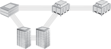
Mesh Interconnect
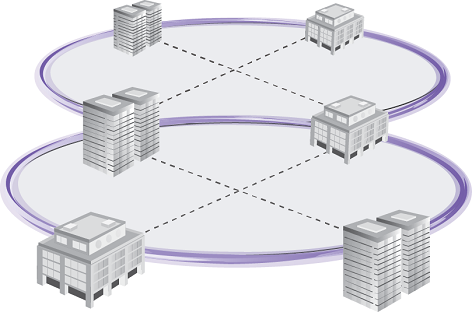
Problem: Rapid data center growth and the addition of buildings and customers may prevent data center operators from knowing the future building locations where they will need connectivity. As these needs arise the optical transport network needs to be flexible enough to support connections between and among all the metro data center locations both new and old.
Solution: Build an optical transport network capable of adapting to the changing environment. This requires flexibility of chassis size, data rate, protocol, wavelengths, management and other parameters.
Benefit: Pay for only those links that are needed and gain the peace of mind and flexibility to create any other links to local or distant locations as the needs arise without limitation.
Description: Equipment or chassis size (rack units) and power consumption are two key aspects to consider when evaluating data center interconnect solutions. A wide selection of chassis options is another important factor. Small chassis are effective for smaller or satellite data centers. Internet exchanges or meet-me rooms may also require smaller size chassis to minimize rack space in situations where space is expensive or crowded. Conversely, large chassis are the best option when the greatest flexibility is required for core sites and when many links, multiple protocols and growth are anticipated.
Mesh optical connectivity often uses advanced features like ROADM and OTN that provide the flexibility to build any network topology and service. Management capabilities enabled by an intelligent control planes using GMPLS and supporting APIs for SDN control are often a factor in more complex optical network designs.
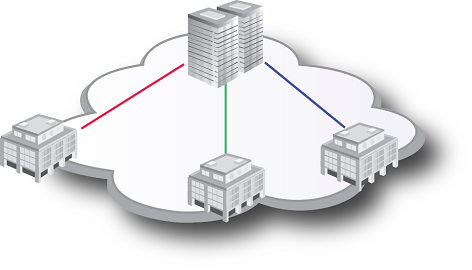
Multi Protocol Interconnect
Problem: Cross-connection between multiple communication service providers and customers at a data center meet-me room or Internet Exchange often requires support for a number of common protocols or standards including: Carrier Ethernet 2.0, SDH, SONET, Fibre Channel or Infiniband.
Solution: To meet this requirement an optical transport network must offer a wide variety of interface options. Solutions that enable the addition of a few or many ports of varying data rate and protocol offer the best value since they ensure that any option is available if the need arises. In addition to offering a wide selection of protocols and number of ports per card, the ability to add amplification, dispersion compensation, and active or passive multiplexing can be valuable when addressing the many issues that can arise when transporting a number of protocols.
Benefit: This strategy ensures that no matter what customers may come to the data center in the future, there is an efficient and cost effective method of connecting them to any service provider.
Description: Consider solutions that offer a wide range of input/output data rates and formats. Optical interfaces from greater than 200G Ethernet all the way down to multiplexed T1 or E1 are available. Some systems offer multi-rate and multi-protocol interfaces that can reduce the number of modules used in the system, minimize sparing costs, and decrease the likelihood of installation error. Other transponders offer features that increase network design options including modules with multiple linked I/O ports on an optical switch that enable dual-transponders, client/line protect, and multicast support all from one module.
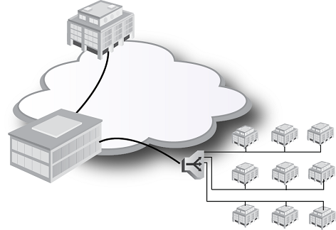
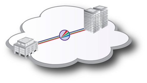
Demarcation for Cloud
Problem: Wavelength services, dark fiber and FaaS (Fiber as a Service) often have little or no method to check the health or performance of the fiber link or the services running over that link. Data centers connected with any of these methods can improve their performance and competitiveness by offering basic performance management on the optical links connecting customers and service providers.
Solution: Providing an optical demarcation device at the customer site provides the opportunity to measure performance and fault management data and then present it in a portal for any user to monitor the performance of their service. This solution is becoming more common in the service provider community and will migrate to data center operators in the near future as customers request this information.
Benefit: Service providers and data centers can offer their current services without any change required but they get the added benefit of reduced troubleshooting costs and the ability to guarantee and prove overall SLA compliance. This can offer competitive advantage now and may be necessary in the future.
Description: Look for systems that can be configured to provide information on optical performance including Digital Diagnostics that may include: Tx/RX, OSNR, power, voltage, temperature and others. In addition, for modules supporting FEC additional performance variables such as BER and frame alignment are available. Carrier Ethernet service performance parameters are another group of performance measurements available for Ethernet links. Some optical transport modules offer a subset of the Carrier Ethernet performance measurements without creating a Carrier Ethernet service.
Conclusion
Data center interconnect is frequently characterized as point-to-point DWDM links with massive bandwidth using many wavelengths. This is one particular use case that is valid for some data center requirements. However, the 7 applications described above are equally important to consider for data center interconnect. Data center business cases are evolving rapidly and so are the optical technologies that support them. Given the dynamic nature of this market, it is smart to build an optical transport network that offers the flexibility to meet new requirements as they arise. Considering these options when designing optical transport networks gives data center operators the options to easily grow their business along with their customers.
Author
 Mannix O’Connor is Director of Technical Marketing at MRV and has held executive positions at Hitachi, Nortel Networks and Bay Networks. Mr. O’Connor was co-chair of the MEF Access committee and the founding Secretary of the IEEE 802.17 Resilient Packet Ring working group. He is a coauthor of the McGraw-Hill publication, “Delivering Carrier Ethernet”. At the Ethernet Academy website he published a peer-reviewed paper on management of DOCSIS PONs.
Mr. O’Connor has spoken on optical networking and switching at Networld Interop, Supercomm, ComNet, Convergence India, Comdex Argentina, and the Congreso Internacional de Telefonia IP Mexico and many other venues. He holds an MBA from George Washington University and lives in San Jose, CA and Denton, TX