
Hollow core fibre (HCF) is emerging as a key technology in the hyperscale and data centre space, one that can deliver ultra-low latencies and low loss links for high-speed interconnects. But deploying this breakthrough technology brings new challenges: complex fibre structures, specialist testing requirements, and the necessity for flawless performance from day one.
In this article, Douglas Clague, Solutions Marketing Manager, Fiber Optic Field Solutions at VIAVI Solutions will outline the benefits of switching from traditional single-mode fibre (SMF) to HCF, and identify seven core challenges that are unique to deploying and testing HCF installations.
HCF versus SMF
Hollow core fibre is a specialist type of optical fibre designed to guide light through an air- or gas-filled central core, unlike conventional single-mode fibre, which uses a solid glass core. There are two main types of HCF, double nested anti-resonant nodeless fibre (DNANF) and photonic bandgap guiding fibre (PBG), each with their own internal hollow core fibre structure and manufacturing process. It is too early to know if there will be a dominant design, but the end goal is the same. These air-guided structures greatly reduce interaction between light and the fibre material, and result in substantial performance advantages. These include faster light propagation and significantly reduced attenuation and signal distortion.
With traditional SMF, data is sent as modulated light through thin strands of solid glass. But natural imperfections and impurities in the glass can cause attenuation of the signal, and for the most demanding applications, this limits how far data can be transmitted before needing amplification.
Compared to single-mode fibre, hollow core fibre enables latencies that are up to 30% lower, and attenuation rates that are up to 65% lower. Additionally, its minimised chromatic dispersion (CD) and nonlinear optical effects result in reduced signal distortion. The air core also allows HCF to handle higher optical powers without thermal damage, which enables transmission over increased distances without the need for amplification and minimal data errors/losses.
While not a replacement for SMF in most standard applications, HCF has moved beyond a lab based technology and is gaining traction in applications where speed, low latency, and high signal fidelity are critical. These include financial trading, where its ultra-low latency provides a critical millisecond edge for high-frequency trading environments; defence and secure communications, where its air-guided structure makes HCF more resistant to physical tapping/hacking; and quantum cryptography, where its low-distortion transmission supports quantum key distribution alongside high-speed encrypted data streams.
But the primary factor accelerating adoption of HCF is the exponential growth in data demands resulting from the AI-driven digital economy, where HCF’s increased transmission speeds, lower latency and lower signal distortion help overcome current bottlenecks. As these heavy processing and networking demands increasingly drive campus-scale and even metro-scale compute setups, HCF enables the data centre interconnects, and distributed supercomputing for multi-node high-performance computing (HPC) tasks such as AI model training.
Because HCF can deliver longer reach without amplification, it can form the backbone routing needed to connect distant regional cloud computing hubs, providing greater geographical flexibility for hyperscalers when locating their AI data centre infrastructure to tap into local power and water resources. HCF will also help future-proof tomorrow’s ultra-high-speed network infrastructure, providing a scalable foundation as 800G/1.6T Ethernet and 5G/6G power the responsive networks needed for autonomous systems, real-time data processing, and edge computing in smart cities.

Fig 1. Double nested anti-resonant nodeless fibre (DNANF) and photonic bandgap guiding fibre (PBG) are the two main types of HFC.
Deployment and testing challenges
Hollow core fibre offers transformative potential for optical networks but its successful deployment hinges on multiple aspects. HCF fabrication is complex and requires advanced techniques, resulting in higher costs, while the fibres themselves can be more mechanically fragile than standard glass fibres.
Notably, deploying hollow core fibre introduces a unique set of challenges that differ significantly from conventional SMF installations, including new variables in splice integrity, bend sensitivity, optical losses, transmission bands, and testing tools. Few suitable testing and certification options currently exist – and proper qualification requires adapting both tools and procedures to account for the distinct physical and optical properties of HCF.
HCF projects therefore demand larger investment and an expanded range of tests due to increased manufacturing, specialist contractor deployment costs and differing optical properties, including backscattering and spectral range.
Key technical challenges include:
1. Process and expertise gaps
Most fibre technicians are trained on SMF systems and may be unfamiliar with HCF-specific handling, testing, and troubleshooting. Training programs and manufacturer support are essential to ensure successful deployment. HCF deployments also lack standardised MoPs (Method of Procedure), making each installation a bespoke process. This increases the risk of inconsistency and requires detailed planning, documentation, and validation protocols.
2. Physical handling and deployment hurdles
HCFs are 10x more mechanically sensitive to bending than SMFs, due to their complex micro-structured design and air-core geometry. Minor routing curves or pull-force strain during installation can damage the internal guiding structures, causing massive optical loss. While SMFs can tolerate a bend radius as low as 7.5 mm, HCFs will require minimum bend radii of several centimeters to avoid excessive attenuation or damage. Installers must ensure proper routing and strain relief to maintain performance.
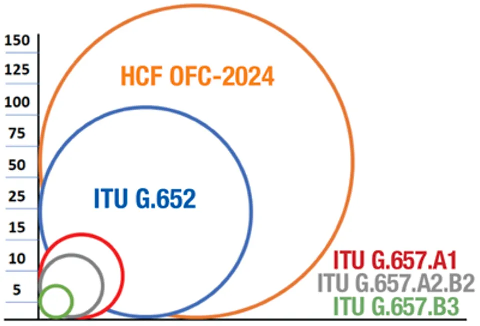
Fig 2. Minimum bending radius HCF vs. ITU G.657 Source: Broadband librar
Splicing and connectivity obstacles
Transitioning from SMF to HCF, for example when connecting OTDR launch and receive fibres to a HCF being tested or coupling HCF to SMF patch cords, introduces coupling inefficiencies due to mismatched mode fields and core geometries. This can be overcome with the use of Mode Field Adapters (MFA) but losses can range from 0.2–3 dB, depending on alignment precision and connector quality. These losses must be carefully measured when commissioning a link. The transition from glass to air can also generate high reflections of up to -15 dB if not properly handled. This can be challenging for an OTDR, generating tailing on the trace and potentially masking some events close to this first connection. It is important to control this first adapter and ensure reflection is as low as possible: ideally better than -50 dB.
Fusion splicing between HCF-to-HCF segments is also more complex and can result in splice losses of 0.1–1.5 dB, depending on fibre alignment and cleanliness. Also compared to SMF-to-SMF splices, HCF-to-HCF splices generate high reflectance which creates dead zones. In the field, splices could be 2–4 km apart, which reinforces the importance of having an OTDR with high dynamic range performance at short pulse widths to be able to measure each of them and not end up with merged results.
Field testing and characterisation
HCF’s exceptionally low Rayleigh backscattering (RBS) levels, approximately 14-20 dB lower than SMF, significantly affect OTDR trace visibility, making it harder to detect events and measure distances. Standard OTDR settings and analysis algorithms to test SMF may fail to correctly analyse or detect key features, requiring modifying testing parameters, such as pulse width and averaging time.
In addition, unlike SMF where backscattering is relatively uniform, HCF will show non-uniform backscattering along the fibre length due to microstructural variations. This complicates OTDR trace interpretation and requires different test settings than for SMF. The variable backscatter coefficient also means that bidirectional OTDR test and analysis is the only method suitable for characterising fibre and splice losses.
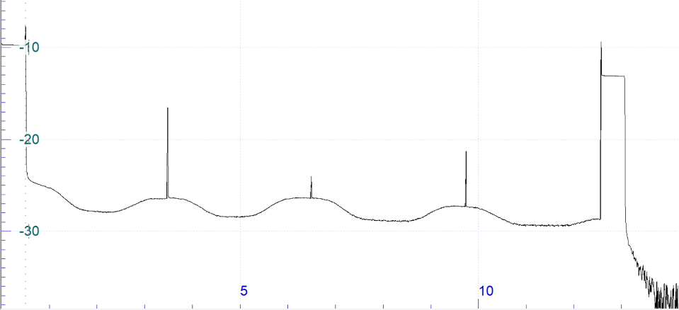
Fig 4. Standard uni-directional OTDR trace showing the variation of RBS coefficient and the reflective splices
Most HCFs are currently optimised for operation in the S-band (starting around 1450 nm) and above. OTDR testing at 1310 nm (typical for standard SMF) will not produce relevant or useful results, so testing at 1550 nm is required. As with SMF testing, using additional wavelengths allows for better fibre and splice loss characterisation and bend detection. Therefore, HCF requires measurements at 1550 nm and 1625 nm for field acceptance testing.
Post-processing analysis
Due to the unique trace characteristics (RBS varying along the fibre), bidirectional OTDR analysis is required – but current standard bidirectional post-processing analysis algorithms may not be optimised for this. Custom software or manual interpretation is often needed to create the loss profile, assess splice quality, connector loss, and fibre integrity. It is therefore necessary to match each point/event from each direction, align the two traces and make a bidirectional analysis, (AB-BA)/2, to obtain the actual loss profile. Loss profile trace obtained by bidirectional analysis will then allow measurement of attenuation for each HCF section and the loss of each splice/event on a link.
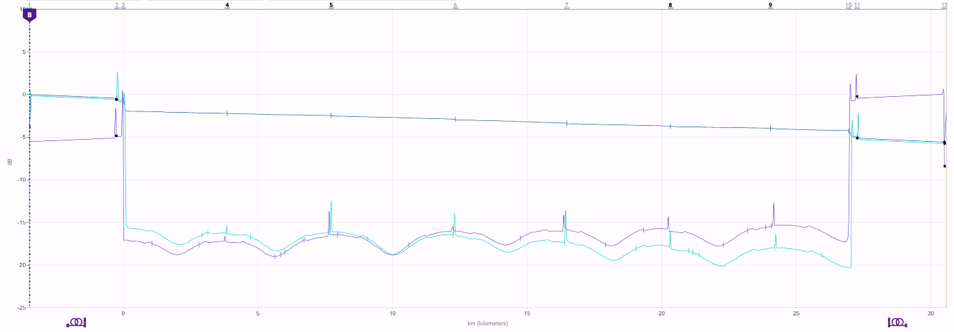
Fig 5. Loss profile trace obtained by performing bidirectional OTDR testing with VIAVI 8100 series OTDR and ReportPRO software
Attenuation profiling
Unlike conventional glass fibres, with well-established and consistent spectral attenuation profiles, HCF is still in the early stages of industrial development. Variations in design, manufacturing processes, and materials across vendors may result in significant differences in attenuation behavior.
Attenuation profile testing helps identify non-ideal transmission characteristics, such as absorption regions caused by water vapor or gas ingress. These non-ideal characteristics can impact system reliability and efficiency. During manufacturing, the presence of any residual atmospheric gas trapped in the core during manufacturing can produce gas-line absorption (GLA): narrow, wavelength-specific loss peaks, most notably from CO₂ in the C/L/U bands. Field profiling assesses link quality and verifies performance claims. In this context, attenuation profiling is not just a technical formality, it is a necessary step to build confidence in HCF deployment and to support informed decision-making in real-world transmission applications.
In addition, HCF operates at low internal pressures, often pre-filled with inert gas. If a cable is cut, left unsealed during deployment, or not managed correctly when splicing, the pressure differential sucks in ambient air, moisture, and atmospheric gases like CO₂. These contaminants block or degrade the transmission windows.
As a result, post-installation testing of the attenuation profile becomes essential to validate the actual transmission capacity of the link, confirm manufacturer specifications, and ensure compatibility with system requirements. This is especially important in applications where wavelength-specific performance is critical.
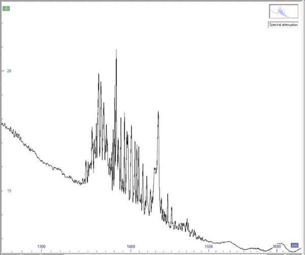
Fig 6. Hollow core fibre attenuation profile measurement obtained via VIAVI’s Optical Dispersion Measurement (ODM) module and Optical Broadband Source
Dispersion effects
HCF is designed to transmit over longer distances and at higher speeds. Dispersion could have an impact on future upgrades of transmission rates, so knowing the real base line is important. Even though dispersion effects are much lower in HCF versus SMF, there is a risk of inconsistency as new HCF manufacturing processes are established. Validation of CD (chromatic dispersion) and PMD (polarisation mode dispersion) parameters ensure nothing unexpected has occurred after splicing all HCF sections together.
However, OTDR-based dispersion tests are limited by the same 14–20 dB drop in Rayleigh backscatter and other dynamic range constraints, making them only suitable for short links. Medium to long haul links are better characterised with a dedicated optical source and dispersion measurement device.
Why testing matters more than ever
Existing test solutions and methods aren’t obsolete, but they need to be enhanced. Tools with the right performance must be selected. Accurate certification of HCF links requires specialised OTDR configuration and performance, with different bidirectional analysis than SMF to ensure precise splice and fibre loss measurements, and overall link integrity. Accurate link characterisation from day one is essential to guarantee performance, minimise rework, protect ROI, and meet the demanding requirements of ultra-high-speed optical networks. Without this, operators risk performance gaps that can impact mission-critical applications.
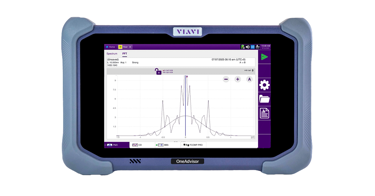
VIAVI’s OneAdvisor 800, the industry's first all-in-one medium- & long-range bidirectional testing & certification solution for hollow core fibre (HCF)